Evaluation of Circularly Polarized Organic Light Emitting Diode using a CPL Measurement System
December 18, 2025 Download This Application
Introduction
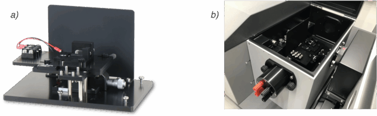
A CP-OLED emits circularly polarized luminescence (CPL) under an applied voltage and has potential applications in devices such as 3D displays and lights for plant growth.1 In this study, evaluation of the properties of CP-OLEDs is performed using a CPL measurement system with a dedicated accessory that allows easy alignment of the optical axis of the device and simple electrode wiring, so that stable measurement can be performed (Figure 1). In this report, we describe the use of this accessory to evaluate the CPEL properties of a CP-OLED device with fac-Λ-Ir(ppy)3 as an emitting layer.
Experimental
Sample
CP-OLED device with fac-Λ-Ir(ppy)3 (Figure 2) as emitting layer
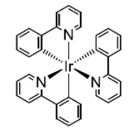
(Light-emitting area: 2 mm x 2 mm)
System
Instrument: CPL-300 CPL measurement system
Accessory: Dedicated CP-OLED accessory*
Software: Spectra measurement program
*This product is a custom-ordered item.
Parameters
| Em. Bandwidth | 10 nm | Scanning Speed: | 100 nm/min |
| Response: | 4 s | Data Interval: | 0.5 nm |
| Accumulations: | 2 |
Measurement Procedure
Figure 3 shows the measurement procedure using the dedicated CP-OLED accessory.
- Confirm optical emission
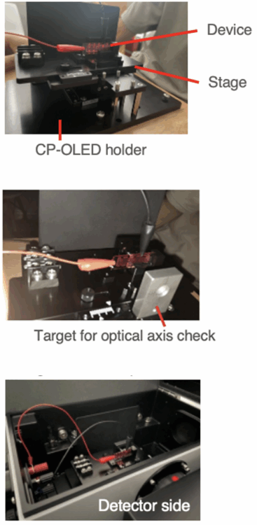
Fig. 3 Measurement procedure
Place the device on the stage outside the sample compartment
and confirm that it is emitting light under an applied voltage
- Adjust device position
Adjust the vertical and horizontal positions of the stage using
the target for checking the optical axis.
3. Place the CP-OLED holder containing the device sample in the sample
compartment, and apply a voltage to cause optical emission.
- Start CPL and EL measurements
Close the lid of the sample compartment and start the CPL and EL measurements.
Keywords
CPEL, CP-OLED, CPL, Circularly polarized electroluminescence, Circularly polarized organic light emitting diode, Circularly polarized luminescence, Device
Results
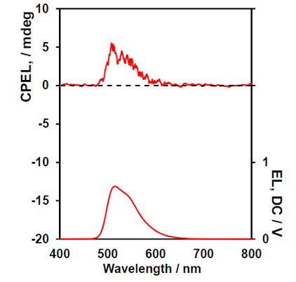
Figure 4 shows a photograph of the CP-OLED device under an applied voltage of 11 V. The device is seen to exhibit strong green light emission. The corresponding CPEL and EL spectra are shown in Figure 5. The EL spectrum has a peak wavelength of 514 nm and a positive CPEL signal is produced.

Conclusion
The CPEL and EL spectra of a CP-OLED device with fac-Λ-Ir(ppy)₃ as the emitting layer and an emission area of 2 x 2 mm were measured using a dedicated CP-OLED accessory. This accessory allows easy alignment of the optical axis of the device and simplifies electrode wiring, so that stable CPEL measurements can be performed.
References
This work was performed under the guidance of Prof. Yoshitane Imai, Faculty of Science and Engineering, Kindai University.
- D.-W. Zhang, M. Li, C.-F. Chen: Chem. Soc. Rev., 49, 1331 (2020). DOI: 10.1039/C9CS00680J