Myths and Facts: Sampling Frequency, Response Time, and Extra-Column Effects in HPLC
November 6, 2024Introduction
Abstract
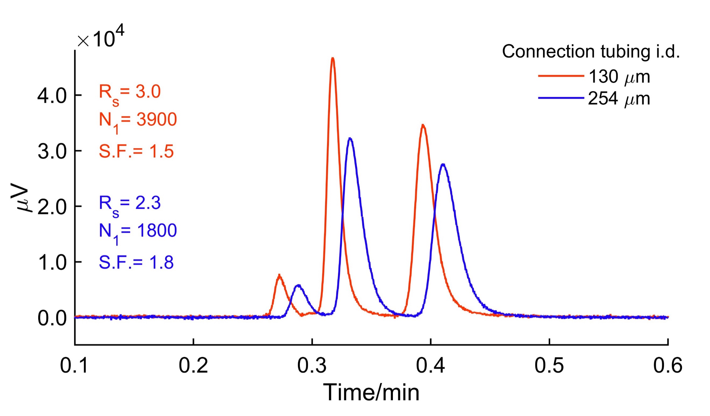
Sampling frequency, often measured in Hertz (Hz) or sampling interval in seconds, conveys how many data points are collected per second or the time spacing between each data point, respectively. Currently, some HPLC-UV detectors can offer up to 160-250 Hz, and analysts tend to prefer higher sampling rates. Over five decades, varying viewpoints have emerged, but a comprehensive perspective remains elusive. Analytical chemists commonly use a heuristic approach of 15-20 data points per peak for accurate quantitation. This review connects the Nyquist-Shannon sampling theorem to chromatographic data, emphasizing the importance of appropriate sampling rates to capture crucial features without distortion, unnecessary noise, and oversampling. It is demonstrated that most features of even an ultrahigh efficiency chromatogram have relatively low-frequency components. Thus, 100 Hz is sufficient for all fast and ultrahigh efficiency separations. Oversampling also increases unwanted noise. Similarly, another confusing concept is the deceptive relationship between sampling frequencies and response times. We show that there is no connection among them. Non-optimal response times will affect peak-to-peak resolution. Also, the importance of extra-column band broadening is emphasized. Peak efficiency loss can be as high as 50% if the tubing internal diameter is changed from 130 µm to 254 µm.
Keywords: HPLC, RHPLC, UHPLC, chromatography
M. Farooq Wahab, Siddharth Jaya Sajeevan J, Daniel W. Armstrong
Department of Chemistry and Biochemistry, University of Texas at Arlington, 76019, USA
Introduction
One of the most debated topics in instrumental analysis is the optimum data sampling frequency for chromatographic detectors. The sampling frequency is often quoted in Hertz (Hz) units, or some instrument manufacturers also quote sampling intervals in seconds. Both convey the same information; the former suggests how many data points are collected per second, and the latter shows the time spacing between each data point. This concept for chromatography detectors has been under discussion for over five decades, with various authors frequently presenting differing viewpoints supported by their own examples, experiences, and available instrumentation technology of their time [1-8]. However, a comprehensive and universally applicable perspective on this topic is often lacking. A widely used rule of thumb among analytical chemists is that a minimum of 15-20 data points per peak is necessary to accurately describe peak shapes and ensure precise quantitation by peak areas [9]. This heuristic rule is established in the need to capture all the features of chromatographic peaks, including their area, width, height, and symmetry, with high accuracy. This notion, although practical, has an empirical basis. However, the fundamental criteria must be addressed for a proper understanding.
Most detectors used in chromatography generate a continuous electrical signal using light detectors, e.g., absorbance detectors measure changes in light intensities before and after absorption. The analog-to-digital converter digitizes this analog signal to sample signals discretely and sends it to a computer. Very few chromatographers have invoked the Nyquist-Shannon sampling theorem in their detector sampling rate discussions [1, 5]. In the original words of the 1949 work of Shannon [10], theorem 1 is stated as, “If a function f(t) contains no frequencies higher than W cps (cycles per second), it is completely determined by giving its ordinates at a series of points spaced 1/2 W seconds apart.” This rule tells us that reconstructing a bandlimited sampled signal without loss of information requires uniformly sampling at least twice the signal bandwidth. Suppose we wish to sample a sine wave that contains only 5 and 32 Hz oscillations. Nyquist criterion tells us that the maximum frequency component here is 32 Hz, so we must choose at least 2×32 Hz = 64 Hz to reconstruct the signal with complete fidelity. Selecting a sampling frequency less than 64 Hz will lead to undersampling, and anything above that will be termed oversampling.
As mentioned above, the sampling theorem can now be connected to a chromatographic system to sample a continuous chromatogram from the detector. In the context of chromatographic data, the time-domain signal represents the detector response as a function of time, capturing the elution profiles of various analytes. To apply the Nyquist criterion to HPLC data, we need to analyze the signal in the frequency domain to see what frequencies are present in a chromatogram. This conversion between domains is facilitated by a mathematical technique known as the Fourier Transform (FT). The FT decomposes a time-domain signal into its constituent frequency components, providing a spectrum that illustrates the presence and intensity of different frequencies within the signal collected in time [11]. This observation, in turn, allows us to pick the appropriate sampling rate using the Nyquist criterion. For example, if most useful frequencies are concentrated until 10 Hz and the rest are mainly noise, we must at least sample the data above 2×10 Hz as a reasonable starting point.
Understanding these frequency components is essential for determining the appropriate sampling rate, ensuring that all significant chromatographic features are captured without shape distortion, loss of peak area and height information. The question then arises: should we invest in an HPLC/CD/SFC detector with the highest possible sampling rate, such as 160 Hz, 250 Hz, or even 1 MHz, if it becomes available in the future? This application note aims to explore these considerations in greater detail, providing insights and recommendations based on current research and technological advancements in the field. There is a trade-off: undersampling a chromatogram is dangerous as information loss is permanent. Conversely, oversampling is unnecessary because it captures more electronic noise and makes the file sizes large. Other factors, such as response times and extra-column volumes, should also be considered to obtain the best information from a given chromatograph.
Experimental
The JASCO RHPLC was equipped with a binary pump (PU-4180), a degasser, an active mixer, autosampler (AS-4150) with a 5 µL sample loop, column oven (CO-4062), and photodiode array detector, PDA, (MD-4010) with a flow cell volume of 2.8 µL. The flow cell was a semi-micro SP flow cell. Columns: TeicoShell, 50 mm x 4.6 mm i.d. column, was packed with 2.7 µm superficially porous silica particles (SPP) bonded to teicoplanin was obtained from (AZYP, LLC, Arlington, Texas). Chemicals: HPLC grade methanol was purchased from Fisher Scientific (USA), and racemic 5-methyl-5-phenylhydantoin standard (CAS No. 6843-498) was obtained from Aldrich (USA). Mobile phase compositions refer to volume-by-volume (v/v) compositions. A single pump was used for solvent delivery. The maximum sampling rate available in this PDA detector is 100 Hz, with five response (time) settings called U.Fast, Fast, Std Slow, and U.Slow. The letter U refers to ultra. The JASCO RHPLC was used for the analysis of an ultrafast (30 s) chiral separation. The tubing connections from the autosampler to the column and column to the detector were SST NanoViper tubings. The autosampler-to-column length is 450 mm L x 0.13 mm i.d., and the column-to-detector tubing dimensions are 250 mm L x 0.13 mm i.d.
Data from a UHPLC and an HPLC were also used for the frequency analysis of high-efficiency chromatograms obtained from previous works. The UHPLC A has a maximum sampling rate of 160 Hz with an associated response time of 0.016 s. A sub-minute UHPLC separation was performed with a 150 mm L x 4.6 mm i.d. column packed with 2.7 µm C18 bonded silica with 80/20 ACN/H2O. The efficiencies of uracil and phenol were evaluated in the reverse phase mode. The HPLC B has a maximum sampling rate of 80 Hz with an associated response time of 0.031 s. HPLC B was evaluated for a high-efficiency HILIC separation of uracil, adenosine, and cytosine with a mobile phase of 75/25 ACN/ H2O (in 25 mM ammonium acetate).
Computations/Software: MATLAB R2023b was used for discrete (fast) Fourier transform using the “fft” function. The magnitude spectrum is scaled with the number of data points, N. The power spectrum is simply the raw fft magnitude squared divided by N2 using the convention outlined here (https://www.dsprelated.com/showarticle/1004.php). More details on discrete Fourier transformations specifically for chromatography can be found in reference [11]. Note that the discrete Fourier transform helps analyze uniformly sampled data.
Results
Frequency Analysis of High-Efficiency Chromatograms by Fourier Transform.
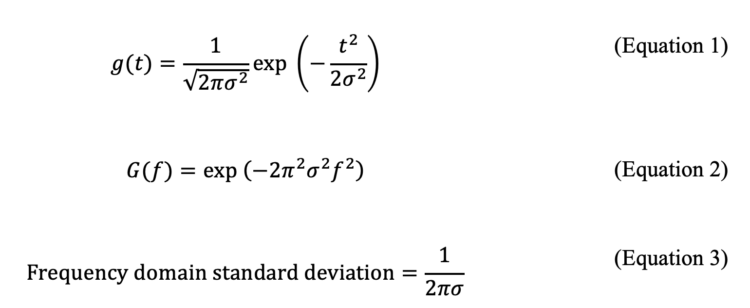
The discussion should begin with a significant mathematical result relevant to addressing the sampling rate issue. Let g(t) be a Gaussian distribution with a standard deviation of σ as a function of time, t. Suppose we have a unit area Gaussian shown in equation (1) and its corresponding Fourier transform, G(f), (which can be obtained from Mathematica software) in equation 2. Here f represents frequency in Hz.
A quick examination of the two equations demonstrates that the Fourier transform of a Gaussian function is another Gaussian function in the frequency domain, with the width in the frequency domain inversely proportional to the width in the time domain (equation 3). This observation means a narrow Gaussian peak in a chromatogram will appear as a broad Gaussian peak in the frequency spectrum. A narrow chromatogram peak must then be sampled at a higher sampling rate as per the Nyquist criterion. A further examination of the two equations (1-2) reveals that the Gaussian distribution does not have a start or an end. It extends indefinitely to -∞ and +∞ in both directions; however, a nice property of Gaussian distributions, unlike many other peak shapes, is that 99.99366% of the peak area is within ±4σ. In reality, peaks can have some degree of asymmetry, and if we choose one-sided 10σ in the frequency domain, we capture all the peak area information. This point will be illustrated below.

We investigated the frequency components of modern high-efficiency reverse phase chromatograms obtained on two different chromatographs using discrete Fourier transform [11]. Today, with the advent of sub-2 micron or core-shell particles, obtaining 25,000-40,000 plates per column is being observed routinely. What frequency components do such chromatograms have? Figure 1 A shows a HILIC separation of uracil, adenosine, and cytosine on a a 2.7 µm FructoShell-N column (150 mm L x 4.6 mm i.d.), on a standard HPLC B, whose maximum sampling rate is 80 Hz. The observed efficiencies are 25,550, 22,900, and 24,800 of peaks 1, 2 and 3. The standard deviation of the peaks are 0.733, 0.935, and 1.017 s. In the Fourier transform, the standard of the narrowest Gaussian, peak 1, will be 1/2п(0.733) s = 0.217 Hz in the frequency domain. The narrowest will have the broadest contribution in the frequency domain. If the Gaussian width is captured up to one-sided 10σ = 2.17 Hz, which is very safe to capture 10 standard deviations, then by Nyquist’s criterion, we can sample above 2×2.17 Hz ~ 4.4 Hz without losing any significant information. Figure 1B shows the magnitude spectrum of this chromatogram. Note the wiggles, not a Gaussian as per equation (3), because multiple time-shifted Gaussians are present. As is apparent, most useful frequencies are present below 1 Hz. The power spectrum, Figure 1C, magnifies these effects on a log scale. Similarly, the power of the signal is concentrated below 1 Hz. Therefore, sampling at 80 Hz is essentially oversampling, and sampling at 10-20 Hz should have been more than sufficient.
The second case is also challenging in terms of high efficiency and speed. The column manufacturer states the 150 mm L x 4.6 mm i.d. column efficiency is ~ 40,000 plates under a minute (Figure 1D). The chromatogram was obtained on a UHPLC A, whose maximum sampling rate is 160 Hz. Let us analyze the peak standard deviations in seconds. The σ of peaks 1′ and 2′ are 0.226 and 0.268 s, respectively. Using the same arguments as above, capturing up to one-sided 10 standard deviations, the frequency domain cut-off will be 7.067 Hz, and by Nyquist criterion, 2×7.067 Hz =14.13 Hz is sufficient to capture the information of the narrowest peak in the chromatogram. This estimation is a very safe sampling margin; thus, 160 Hz was an excessive oversampling choice, made intentionally for illustration purposes here. Figures 1E-F show the corresponding magnitude and power spectra of the frequency components of this ultrahigh efficiency chromatogram from the discrete FT. Note that most of the power is concentrated below 6 Hz. It should be clear to the readers that even state-of-the-art instruments and columns do not need an oversampling rate above 100 Hz for most separation cases. The most useful information is found at reasonably low frequencies in the discrete Fourier transform.
Visual Effects of Oversampling and Undersampling an Ultrafast Chiral Separation on a Short Column using a JASCO PDA Detector
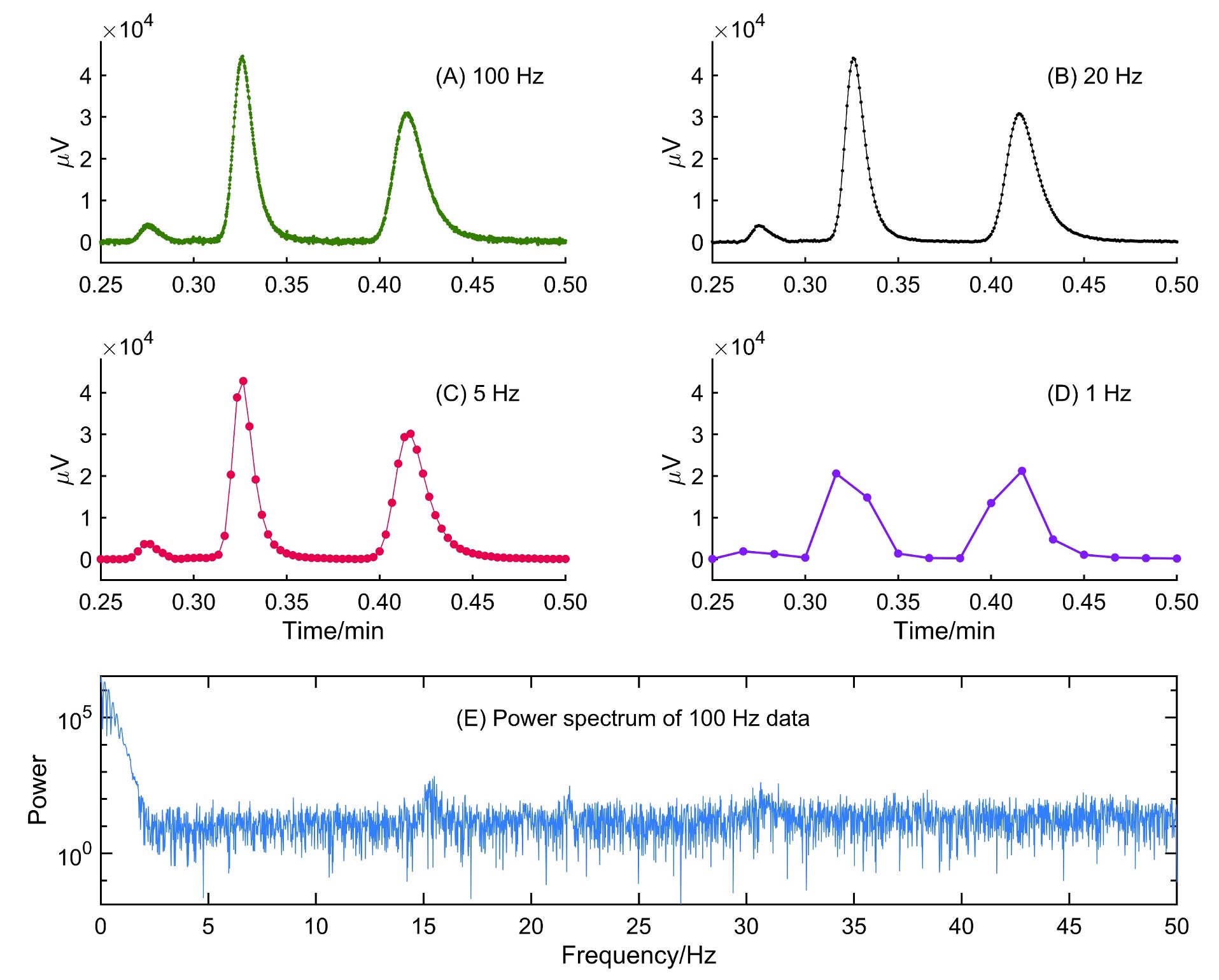
The PDA detector of JASCO RHPLC has a maximum sampling rate of 100 Hz, and the user can independently choose the sampling rate along with the response times. The available sampling rates are 100, 50, 20, 10, 5, 2, 1, 0.5, and 0.25 Hz, allowing sampling for a wide range of peak widths, without severely oversampling data. The issue of response time will be addressed in the next section. As shown above, most ultrahigh efficiency columns and even sub-minute separations will never need a 100 Hz data sampling rate. The standard deviation of the narrowest peak determines the highest sampling rate in a chromatograph. In order to further visualize this idea, we show an example of a sub-minute racemic separation of 5-methyl-5-phenylhydantoin. The separation was conducted with a 50 mm L x 4.6 mm i.d. column packed with 2.7 µm SPP bonded to teicoplanin (TeicoShell). A survey chromatogram was collected at 2 mL/min MeOH, the data collection rate set to 100 Hz, and the U.Fast response time (Figure 2A). Fourier transform of the chromatogram indicated that useful frequencies are below 5 Hz. This means a sampling rate > 10 Hz should be sufficient for this fast separation. Figure 2B shows sampling at 20 Hz, and it is a perfect reconstruction with less noise than 100 Hz. However, at 5 Hz, we are reaching the critical point of Nyquist. At 5 Hz (Figure 2C), peak segmentation becomes visible. Below 5 Hz, we violate the sampling rate theorem, and information loss is evident. The power spectrum in Figure 2E supports all these observations.

Independent Variation of Sampling Rate and Response Time in JASCO Detector
Many researchers often mix the concept of sampling rate with response time, resulting in incorrect conclusions [4]. The sampling rate and response times are independent concepts and have reciprocal units, which leads to a deceptive relation between them. There is no relation between sampling rate and response time; however, optimizing these parameters are necessary for good chromatography. Some chromatograph manufacturers do not allow independent choices in sampling rate and response time; thus, the user must keep this potential pitfall in mind. As explained in the introduction, sampling rate tells us the number of points collected per second, whereas response time is the time it takes for a detector to respond from 10% to 90% of a unit step function, as shown in Figure 3A. In Figure 3B, moving average windows are applied using 5, 15, 51, 251, and 351 points on the step function data corresponding to the lowest to the highest response time. The response time can be seen from t10% to t90% going from 0.1 s to 0.89 s = 0.79 s, which is a relatively slow response time for fast chromatographic work. Note that the effect of shifting the signal and the relevance of this shift will become visible soon. In Figure 3C, random noise has been added, and then the effect of moving averages becomes evident in Figure 3D. The larger the response time, the higher smoothing we see on the noise levels. The purpose of selecting a response time in a chromatographic method is to suppress noise. A larger response time means more smoothing, and a smaller response time means less smoothing by a digital filter [5]. The sampling rate and response times are not fundamentally connected. Most confusion has arisen because many researchers have mixed the concepts of sampling rate and response times [5].

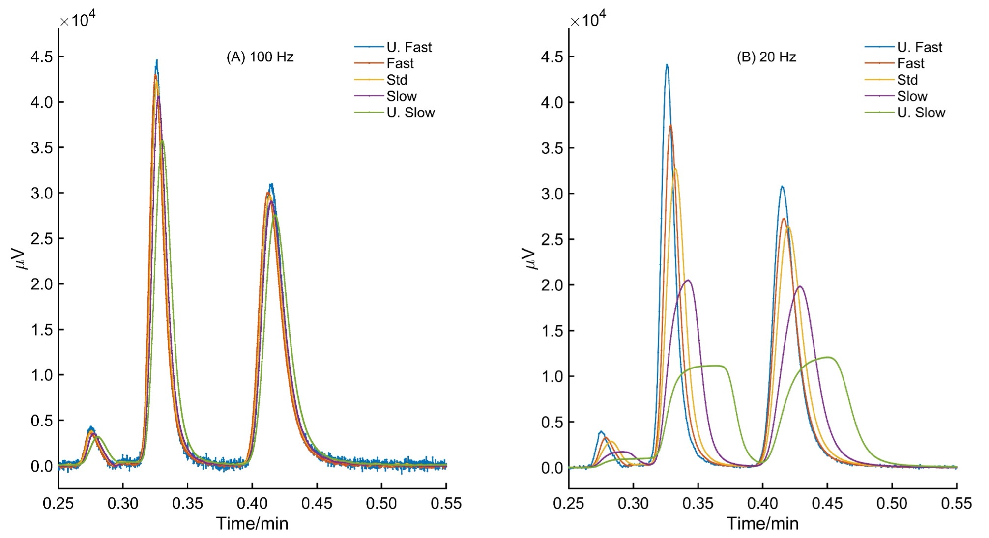
Figure 4 shows the effect of keeping the sampling rate the same for the ultrafast racemic separation of 5-methyl-5-phenylhydantoin in 30 seconds with five response time settings. The settings are U.Fast, Fast, Std, Slow, and U.Slow. The window size is not disclosed in ChromNav. The sampling rate is well above the Nyquist criterion, i.e., 100 and 20 Hz. With 100 Hz, the effect of response time is minimal, but as the number of data points decreases, as in 20 Hz, the effect of response time settings becomes significant. Above the Nyquist sampling rate, the response time choices will also impact the peak shape. Note that the peak area remains unchanged since this denoising is based on convolution. There is no loss of area information; however, incorrect response time choices during method development will lose the original peak shape. Table 1 summarizes the changes in chromatographic efficiency as inappropriate response times are selected.

| Response Time Setting | ||||
| U. Fast | ||||
| Fast | ||||
| STD | ||||
| Slow | ||||
| U.Slow | ||||
Table 1. Effect of choosing inappropriate response times on a fast separation even if we are above the Nyquist sampling rate. See Figure 2 for corresponding chromatograms.
Importance of reducing extra-column volumes in fast or high-efficiency chromatography
Extra-column volume is the chromatographic instrument volume from the injection port to the flow cell volume minus the chromatographic bed. Thus, sample loop, connection tubings from the injector, column connecting screw caps, inlet and outlet frit of the packed bed, tubings leading to the flow cell, and flow cell volume all contribute to these extra-column volumes [12]. Extra-column volume adversely impacts the peak width (i.e., efficiency) and shape. These effects were initially pointed out in gas and liquid chromatography decades ago [13-15]. All standard liquid chromatographs still exhibit some extra-column band-broadening effects because having a sample loop, connections, tubings, frits, and a flow cell with zero volumes is physically impossible. A good analyst can only minimize these effects, not eliminate them, even using state-of-the-art chromatographs. The sample plug broadens in the injector needle and tubing, which connects to the column from the sample introduction port. Upon reaching the column head, the inlet frit further broadens the sample band. Additional band broadening occurs at the exit frit and in the post-column tubing and connections, leading to the detector. The flow cell geometry and digital signal processing finalize the observed peak shape. Note that column packing does not include extra-column effects due to flow profile inhomogeneities.

Similarly, the JASCO RPLCs can be optimized for extra-column volumes using well-cut tubings with a flat end and narrow internal diameters. The detector in JASCO RHPLC was a semi-micro flow cell with a volume of 2.8 µL. Figure 5 shows the dramatic effect of changing the tubing diameter from the autosampler to the column and column to the detector from 130 µm to 254 µm. The sampling rate, response time, and tubing length in each case were kept constant. The separation, obtained with 130 µm i.d. tubing, showed a plate count of 3900 for the first enantiomer of 5-methyl-5-phenylhydantoin and a resolution of 3.0. These figures of merits decreased to 1800 plates and a resolution of 2.3 just from a poor choice of tubing diameters. Therefore, the users must be aware of such tripping points in fast or high-efficiency liquid chromatography. Also, note the shift in the retention time. The increased retention time is due to the additional volume contributed to the system by the 254 µm i.d. tubings.
Overall Optimization Strategy for Detector Settings and Minimizing Extra-Column Effects
What conclusions can we draw from all the above observations? As equations (1-3) show, the narrowest peak will determine the maximum sampling rate in a chromatogram. Always oversample the data since undersampling means we have lost the peak information permanently. There is no way to recover it by any means. Nevertheless, oversampling should not be done at the highest sampling rate available in a chromatograph. The key reason is that oversampled data will have more and more noise and file size can grow very quickly. The response time should be as small as possible for fast and high-efficiency separation (especially sub-minute separations). Selecting a small response time will not distort the peak shapes, but the trade-off is noise. However, ChromNav also allows users to denoise the data post-processing. Denoising can always be done later, if required. Beware that some manufacturers will have the sampling rate and response times combined [5]; however, JASCO conveniently provides users this flexibility to independently choose a sampling rate and response time.
The next most important thing to remember is to use the smaller diameter tubings with a flat cut. Too narrow tubings (e.g., < 100 µm) can clog easily and generate high back-pressure. The pressure drop in a tubing varies inversely as the tubing diameter squared. Extra-column effects can be mathematically reduced [16]. With correct choices of sampling rate, response times, tubing diameters, injection volumes, and high-efficiency particles, the analyst will get the maximum benefit from their chromatographs for fast and high-throughput separations.
References
[1] P. Kelly, G. Horlick, Practical considerations for digitizing analog signals, Analytical Chemistry 45(3) (1973) 518-527.
[2] J. Anderson, Data acquisition and processing for high speed liquid chromatography, Journal of Liquid Chromatography 6(14) (1983) 2809-2828.
[3] A.C. Brown, D.L. Wallace, G.L. Burce, S. Mathes, Data handling for LC detectors, Liquid Chromatography Detectors, CRC Press 1983, pp. 355-412.
[4] A. Felinger, A. Kilár, B. Boros, The myth of data acquisition rate, Analytica Chimica Acta 854 (2015) 178-182.
[5] M.F. Wahab, P.K. Dasgupta, A.F. Kadjo, D.W. Armstrong, Sampling frequency, response times and embedded signal filtration in fast, high efficiency liquid chromatography: A tutorial, Analytica chimica acta 907 (2016) 31-44.
[6] T. Hetzel, T. Teutenberg, C. Portner, J. Tuerk, Requirements of LC‐hardware for the coupling of different mass spectrometers, The HPLC Expert II: Find and optimize the benefits of your HPLC/UHPLC (2017) 171-192.
[7] W. Zeng, K.P. Bateman, Quantitative LC–MS/MS. 1. Impact of points across a peak on the accuracy and precision of peak area measurements, Journal of the American Society for Mass Spectrometry 34(6) (2023) 1136-1144.
[8] K. Lawlor, J. Clausen, A. Johnston, A. Edge, K. Wolff, E. Castrignanò, L. Couchman, A review of analytical parameters in rapid liquid chromatographic methods for bioanalysis: Can we do better?, Journal of Chromatography A (2024) 464803.
[9] R. Pauls, L. Rogers, Comparisons of methods for calculating retention and separation of chromatographic peaks, Separation Science 12(4) (1977) 395-413.
[10] C.E. Shannon, Communication in the presence of noise, Proceedings of the IRE 37(1) (1949) 10-21.
[11] M.F. Wahab, F. Gritti, T.C. O’Haver, Discrete Fourier transform techniques for noise reduction and digital enhancement of analytical signals, TrAC Trends in Analytical Chemistry 143 (2021) 116354.
[12] G. Desmet, K. Broeckhoven, Extra-column band broadening effects in contemporary liquid chromatography: Causes and solutions, TrAC Trends in Analytical Chemistry 119 (2019) 115619.
[13] H. Elgass, H. Engelhardt, I. Halász, Reproduzierbare Methode zum Packen von Trennsäulen für die Chromatographie mit Kieselgel (5–10 μm), Fresenius’ Zeitschrift für analytische Chemie 294(2) (1979) 97-106.
[14] V.R. Reid, R.E. Synovec, High-speed gas chromatography: The importance of instrumentation optimization and the elimination of extra-column band broadening, Talanta 76(4) (2008) 703-717.
[15] V. Maynard, E. Grushka, Effect of dead volume on efficiency of a gas chromatographic system, Analytical Chemistry 44(8) (1972) 1427-1434.
[16] T.T. Handlovic, M.F. Wahab, S. Roy, R.E. Brown, D.W. Armstrong, Automated regularized deconvolution for eliminating extra-column effects in fast high-efficiency separations, Analytical Chemistry 95(29) (2023) 11028-11036e

 Download This Application