Absolute Reflectance Measurement for V-700 Series UV-Visible and Near Infrared Spectrophotometers

Absolute reflectance measurement is used to evaluate the spectral properties, film thickness, angular variation or other characteristics of samples such as semiconductors, thin films and optical elements.
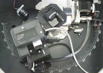
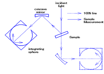
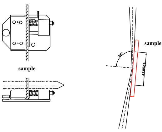
The absolute reflectance measurement accessories are designed to measure the absolute reflectance of a specular reflecting sample (metals, semi conductors, display screens or other materials) while varying the incidence angle (all models). Several models are  used to measure the transmittance of a sample (without diffuse transmittance). Absolute reflectance and transmittance are measured by rotating the sample stage to select an angle of incidence for the light to the sample and setting the detector to measure the reflected light or transmitted light.

Diffuse reflectance can also be measured by placing the sample at the rear of the integrating sphere with an incidence angle of 0º. Diffuse transmittance can be measured by placing the sample at the entrance of the integrating sphere with the incident angle set to 0º.

Effects of Polarization when Measuring Absolute Reflectance

Light from a spectrophotometer that employs a grating is always polarized. The ratio of the intensities of the S and P polarized light varies according to the wavelength and also differs from one grating to another. Greater angles of incidence result in greater difference in the intensity of the S and P polarized light making measurement less accurate. If the absolute reflectance is measured at a high angle of incidence, a polarizer can be set to 45° to minimize the difference in polarization.

Overview of the Range of Absolute Reflectance Measurement Accessories

Manual Measurement

Reflectance Measurement Only

absolute reflectance

The incidence and collection angles are maintained at the same ‘synchronous’ angle by simultaneously rotating the sample stage and integrating sphere. The ARV-913, ARN-914 and ARN-915i are used to measure the absolute reflectance of a specular reflecting sample or the relative reflectance of a diffusely reflecting sample. Transmittance is measured using an optional solid sample holder. An integrating sphere is used with integrated detector(s). The angle of incidence of the sample is set by moving the integrating sphere (in the measurement of absolute reflectance). The angular range of the integrating sphere is 5°to 90°(angle of incidence). Relative reflectance is measured by placing a sample at the rear of the integrating sphere.

Reflectance and Transmittance Measurement

The incidence and collection angles can be set independently in  asynchronous mode. The ARSV-916, ARSN-917 and ARSN-918i manual absolute reflectance measurement accessories measure the absolute reflectance of a reflective sample or transmittance of a clear sample that does not diffuse light. The detector(s) use an integrating sphere and can also measure the relative reflectance or transmittance of samples that diffuse light (the sample holder for relative reflectance is included, a sample holder for transmittance is optional). Absolute reflectance and transmittance are measured by rotating the sample stage to determine the angle of the light incident upon the sample and independently setting the detector angle for the reflected or transmitted light.

Automated Measurement

Reflectance and Transmittance Measurement

absolute reflectance

The incidence and collection angles are set independently in asynchronous mode.The ARMV-919, ARMN-920 and ARMN-921i absolute reflectance measurement systems automate the measurement. The incidence and collection angles can be set in a synchronous mode, by simultaneously rotating the sample stage and integrating sphere. Or the incidence and collection angles can be set independently in asynchronous mode. Using the integrated polarizer the polarization properties of a sample can also be measured using P or S polarization or by adjusting the angles of the polarizer.

Absolute Reflectance Optical Layout

Absolute Reflectance

Absolute Reflectance Diagram

Absolute Reflectance Measurement Accessories

SSH-508 Solid Sample Holder

SSH-508 Solid Sample Holder

This attachment is used to measure the transmittance of a sample that diffuses light.

Sample Size
Min 30 mm (H) x 30 mm (W) x 0.5 mm (D)
Max 70 mm (H) x 80 mm (W) x 10 mm (D)

ARG-476/GPH-506 Polarizers

ARG-476GPH-506

The ratio of the intensities of the S and P polarized light varies according to the wavelength. The greater the angle of incidence of the beam on the sample, the greater the difference in intensity of the S and P polarized light, making measurements less accurate. When the angle of incidence is 30° or greater, a polarizer (optional on the manual systems) is recommended for more accurate measurement .

Wavelength Range:250-750 nm(Model ARV-913)

250-2000 nm(Model ARN-914)

250-1600 nm(Model ARN-915i)
Rotation of Plane of Polarization:0°(linearly polarized light in vertical direction) to 90°(linearly polarized light in horizontal direction)

Wide Incident Angle Sample Holder (up to 85º)

6708-H163A for manual type
6708-H460A for automated type
PDU-755 Phase difference measurement unit (Polarizer with measurement software)