Basic System Configuration of HPLC
An HPLC system is composed of several integrated modules that work together to deliver the mobile phase, introduce the sample, separate components, detect them, and process the resulting data.(Fig. 1). Understanding the flow path helps clarify how each component contributes to reliable and reproducible analysis. Below is a simplified schematic of a typical HPLC flow path:
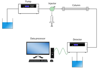
Flow Path Overview
The mobile phase travels from the solvent reservoirs through the degasser and pump, where it is pressurized and delivered at a controlled flow rate. The sample is introduced via the injector or autosampler and carried into the column, where separation occurs. As compounds elute from the column, they pass through the detector, generating a signal that is processed and displayed by the data system as a chromatogram.
Key System Components
Solvent Reservoirs
Hold the mobile phase solvents. These may contain a single solvent (isocratic elution) or multiple solvents blended during gradient elution.
Degasser
Removes dissolved gases from the mobile phase before it reaches the pump.
- Prevents formation of air bubbles in the flow path
- Reduces baseline noise and signal spikes
- Minimizes baseline drift caused by outgassing in the detector flow cell
Degassing improves detector stability and overall system performance.
Pump
Delivers the mobile phase at high pressure through the system.
- Provides precise and consistent flow rate
- Enables gradient mixing when multiple solvents are used
Stable flow is critical for reproducible retention times and accurate quantification.
Injector/Autosampler
Introduces a precise volume of sample into the flowing mobile phase.
- Manual injectors use a fixed sample loop
- Autosamplers automate injections for multiple samples
Accurate injection volume ensures reliable quantitative results.
Column Oven
Maintains the column at a controlled temperature.
- Improves retention time reproducibility
- Enhances seperation consistency
- Can improve peak shape and reduce viscosity-related pressure changes
Temperature stability is especially important for sensitive or highly reproducible methods.
Column
The heart of the HPLC system.
- Packed with stationary phase material
- Responsible for separating compounds based on chemical interactions
Different column chemistries enable different separation modes.
Detector
Monitors compounds as they elute from the column.
Common detector types include UV/Vis, diode array (DAD), fluorescence, and refractive index detectors. The detector converts chemical information into an electrical signal.
Data System
Controls the instrument and processes detector signals.
- Displays chromatograms
- Integrates peaks
- Calculates retention times and peak areas
- Generates quantitative reports
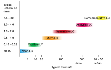
HPLC Pumps
Pumps are classified according to their flow rate (Fig. 2):
- Nano pumps: 1 µL/min or less
- Micro pumps: several tens of µL/min
- Semi-micro pumps: several hundreds of µL/min
- Analytical pumps: several mL/min
- Preparative pumps: several tens of mL/min or more
The pump flow rate for normal analysis is several mL/min.
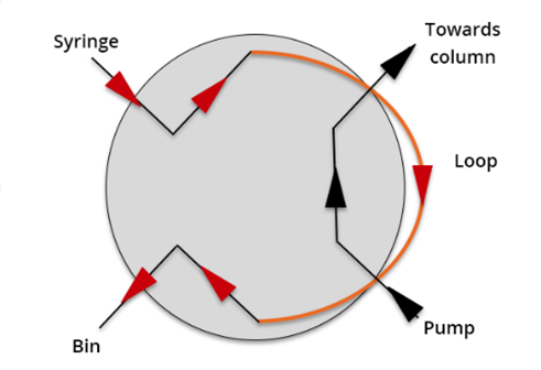
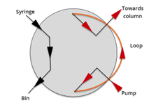
Manual Injection Versus Automatic Sampling
There are two types of sample injector modules: a manual injector and an autosampler. A manual injector requires the user to load and inject the sample via a syringe into the injection valve in the load position to fill the sample loop (Fig. 3). The user then switches the injection valve to the inject position, connecting the sample loop to the pump and column, allowing mobile phase to pass from the pump through the sample loop onto the column (Fig. 4). An autosampler uses an automated injection valve with a mechanism to inject multiple samples sequentially.
Column/Column Oven
The column is where the separation of components in a sample mixture occurs, and this separation is dependent on the temperature of the column. Fluctuations in column temperature will affect sample retention time, selectivity, and peak shape as well as system pressure. To obtain reproducible results, a column oven should be used to keep the column at a constant temperature. A column oven can also be used to increase or decrease the temperature of the column to improve separation. As the temperature of the column increases, the solubility of the sample in the mobile phase increases, resulting in shorter retention times and faster run times. It also decreases the mobile phases viscosity, resulting in a decrease in system pressure, allowing the flow rate of the mobile phase to be increased, which also results shorter retention times and faster run times.
Types of Detectors
As shown in Table 1, there are a variety of detectors that can be used depending on your application needs and the target sample. Ultraviolet (UV) and Photodiode Array (PDA) detectors are commonly used since they cover a wide range of applications and components. When higher sensitivity is required, a fluorescence detector or a Mass Spectrometer (MS) can be used. For a more universal detection of compounds that don’t absorb, or fluorescence, an Evaporative Light-Scattering Detector (ELSD) or a Differential Refractive-Index (DRI) detector is more appropriate.
| Detector Type | Measurement Principle |
|---|---|
| UV/Visible Detector | Absorbance (AU) |
| Photodiode Array (PDA) Detector | Absorbance (AU) |
| Differential Refractive Index (RI) Detector | Refractive Index (RI) |
| Fluorescence Detector | Fluorescence |
| Electrochemical Detector | Oxidation / Reduction |
| Electrical Conductivity Detector | Conductivity |
| Mass Spectrometry Detector | Mass-to-Charge Ratio (m/z) |
| Optical Rotation Detector | Optical Rotation (OR) |
| Circular Dichroism Detector | Circular Dichroism (CD) |
| Evaporative Light Scattering Detector | Light Scattering |