The Use of Dual Spatial Filtration to Improve Spatial Resolution in Raman Imaging Micro-spectroscopy
August 17, 2022
Introduction
Raman micro-spectroscopy has been widely used due to its ability to provide rapid and non-destructive measurements of micron-sized samples. The technique also provides information similar to that of FTIR micro-spectroscopy, offering enhanced capabilities for the analytical laboratory. A primary advantage of Raman micro-spectroscopy over FTIR micro-spectroscopy is better spatial resolution. Comparatively, the minimum spatial resolution for FT-IR measurements is approximately 10 µm, while Raman can easily achieve a spatial resolution of 1 µm.
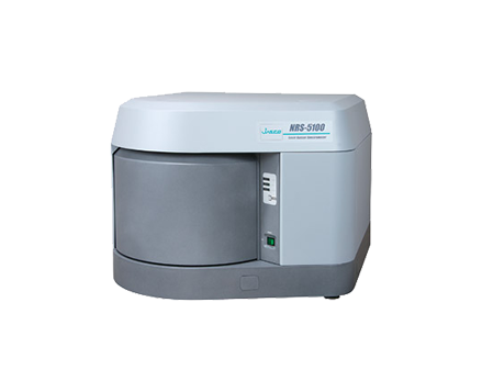
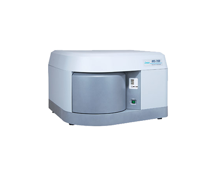
In this application note, the spatial resolution of Raman micro-spectroscopy, its general definition, and evaluation methods will be described. The dual spatial filtration (DSF) system, a standard feature of the JASCO NRS-5000/7000 series Raman micro-spectrometers, will also be explained.
Experimental
Definition of spatial resolution
A laser of a specific wavelength is used as the excitation source in Raman micro-spectroscopy. As the laser beam spot size on the sample is reduced, the spatial resolution at the XY plane increases. When light with a constant intensity distribution is introduced into an objective lens, the diffraction pattern shown in Figure 1 occurs (see page 2). The bright enter area is called the Airy-disk, and its size (d) can be determined from the wavelength (l) and the numerical aperture (N.A.) (see equation in Figure 1). The “d” term refers to the diffraction limit that determines the spatial resolution of an optical microscope.
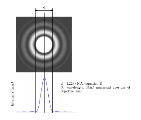
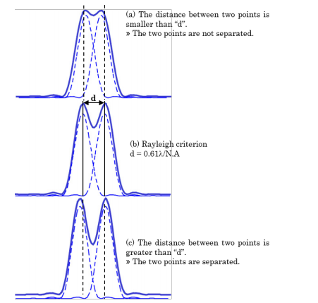
The definition of spatial resolution on an XY plane is based on the distance between two points close to each other — the Rayleigh criterion. In the standard configuration of the JASCO NRS-5000/7000 (532 nm laser, with 100X objective lens and N.A. = 0.90), the laser spot size at the diffraction limit is calculated as d = 720 nm. The spatial resolution, according to the Rayleigh criterion, is then equal to 360 nm.
As the equation in Figure 1 suggests, if the laser wavelength decreases, the spatial resolution then increases. Additionally, if an objective lens such as an oil-immersed lens with a larger N.A. is used, one can expect a comparative increase in spatial resolution.
However, the definition based on FWHM (full width at half maximum) of the intensity of the interference ring has also been recognized. To avoid confusion, when making a comparison of spatial resolution for the Raman micro-spectrometers prepared by different manufacturers, the definition of ‘spatial resolution’ which has been applied should be confirmed. For the NRS-5000/7000 series, each of the values calculated from the two different definitions is shown in Table 1.

Evaluation of spatial resolution in confocal optics
Theoretically, one can calculate the spatial resolution for confocal optics as shown in Table 1. However, the actual value for optical microscopes may become larger due to lens aberrations, the intensity distribution of the incident laser light to the objective lens, as well as other factors.
The actual spatial resolution can be evaluated by measuring the distance of the Raman intensity profile when it changes from 10% to 90% by the measurement of a sample with a sharp edge as illustrated in Figure 3.
This evaluation method was applied to the NRS-5000/7000 series instruments with the standard configuration of a 532 nm laser and an objective lens of N.A. = 0.9. The resulting value was 370 nm, which is very close to the theoretical value of 360 nm calculated according to Table 1.
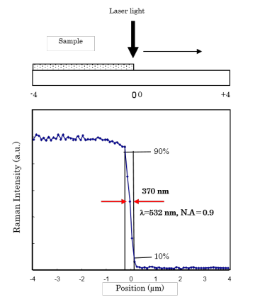
(upper: illustration for measurement of silicon sharp edge / lower: Raman intensity profile of silicon peak
Resolution in-depth in confocal optics
In a confocal optical system, a pinhole aperture is located at a reciprocal focal point of the optical system. Light rays coming from points other than the focus of the objective lens are eliminated.
The depth resolution (dz, where z = resolution) can be determined by the excitation wavelength “λ”, the refractive index “n” of the substrate and the numerical aperture “N.A.” of the objective lens (equation 2).

Inserting the values of “λ” = 532nm, “n” =1 (atmosphere) and N.A.=0.90, a calculated “dz” of 830 nm is obtained.
The actual depth resolution can again be estimated by measuring the FWHM of the Raman intensity profile for a silicon crystal when it is scanned in the Z direction.
In a standard confocal optical system, available with most of the commercially available Raman micro-spectrometers, a typical resolution of 1.5 to 2.0 µm at FWHM is expected. In the NRS-5000/7000, a FWHM of 1 µm can be expected, which is much closer to the theoretical value as shown in Figure 4. This number can be achieved by the use of an improved confocal aperture optimized for Raman spectroscopy.
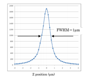
(532 nm laser, objective lens 100X, N.A = 0.9)
Dual spatial filtration (DSF)
The standard dual spatial filtration (DSF) optical system in the NRS-5000/7000 spectrometers has a dual aperture system for confocal optics. This DSF system can eliminate any stray light that was not removed at the first aperture. The DSF method can improve the Z resolution and at the same time, an improvement can be expected in the spatial resolution at the XY plane.
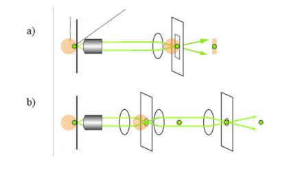
b) JASCO DSF confocal optics
The standard single aperture system (‘a’ in Figure 5) and the JASCO DSF optics (‘b’ in Figure 5) were applied to the measurement of titanium oxide (TiO2) particles on a silicon substrate. The Raman imaging of the peak intensity profile for both results are shown in Figure 7. In this case, the spatial resolution in the XY plane was improved by the use of DSF optics (right image in Figure 7). The image intensity profile was also closer to the microscope image of the sample (Figure6).
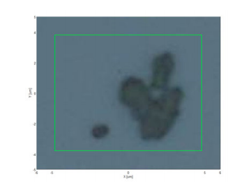
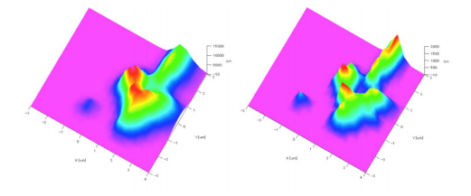
(left; by ordinary confocal system (‘a’ of Figure 5), right; the JASCO DSF system (‘b’ of Figure 5)
The single aperture confocal system and the DSF system were applied to the non-destructive Z scan of a polyvinylalcohol (PVA) layer of a polarizer film to observe the change in the Raman peak intensity of an iodide compound (25 µm thickness) sandwiched between the PVA layers. (Figure 8)
Theoretically, the intensity of the iodide compound peak should rapidly increase when reaching the iodide compound layer then rapidly decrease when again reaching the PVA layer. This is shown by the blue dashed line in the Raman intensity profile displayed as Figure 8. )
The results demonstrate that the profile using the DSF optics (solid red line in Figure 8) is closer to the theoretical profile than the standard confocal system (solid green line in Figure 8). This clearly indicates that the DSF optical system can greatly improve the Z resolution of a confocal optical system.
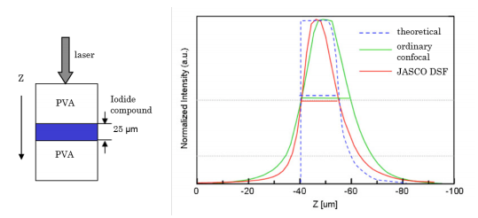
(left: cross-section of multi-layer; right: peak intensity profile of an iodide compound)
Dual spatial filtration (DSF)
The standard dual spatial filtration (DSF) optical system in the NRS-5000/7000 spectrometers has a dual aperture system for confocal optics. This DSF system can eliminate any stray light that was not removed at the first aperture. The DSF method can improve the Z resolution and at the same time, an improvement can be expected in the spatial resolution at the XY plane.
Note
The measurement position in the Z scan becomes shallower (thinner) than the actual sample position (thickness) due to the influence of the refractive index of the substrate. In the case of a 25 µm thickness of the iodide compound layer, the apparent thickness will be approximately 15.3 µm when the refractive index is 1.64. In the NRS-5000/7000, a [Refractive Index Correction] function is available in the mapping data analysis program so that a correction for the difference between the true and measured values can be performed.
Keywords
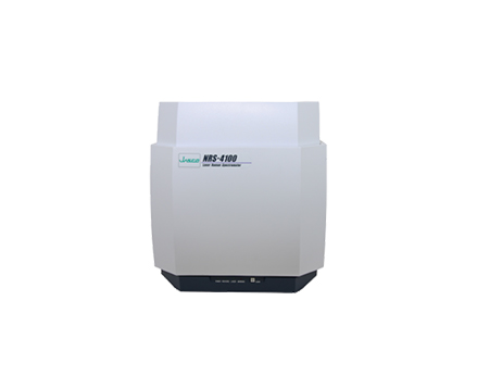
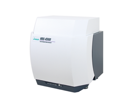
Raman, Raman microscopy, airy disk, Rayleigh criterion, dual spatial filtration, spatial resolution, diffraction limit, NRS-4100, NRS-5100, NRS-5200, NRS-7100, NRS-7200
References
- T. Wilson and C. J. R. Sheppard: Theory and Practice of Scanning Optical Microscopy, Academic Press (1984)
- G. Kino: Confocal Scanning Optical Microscopy and Related Imaging Systems, Academic Press (1996)
- Confocal Laser Scanning Microscopy Principles: ZEISS
- H. Kubota: Hado-Kougaku (written in Japanese) (1971)
- Neil J. Everall, Applied Spectroscopy, Vol. 54, Issue 6, pp. 773-782 (2000)
Featured Products:

The Use of Dual Spatial Filtration to Improve Spatial Resolution in Raman Imaging Micro-spectroscopy
Introduction
Raman micro-spectroscopy has been widely used due to its ability to provide rapid and non-destructive measurements of micron-sized samples. The technique also provides information similar to that of FTIR micro-spectroscopy, offering enhanced capabilities for the analytical laboratory. A primary advantage of Raman micro-spectroscopy over FTIR micro-spectroscopy is better spatial resolution. Comparatively, the minimum spatial resolution for FT-IR measurements is approximately 10 µm, while Raman can easily achieve a spatial resolution of 1 µm.
In this application note, the spatial resolution of Raman micro-spectroscopy, its general definition, and evaluation methods will be described. The dual spatial filtration (DSF) system, a standard feature of the JASCO NRS-5000/7000 series Raman micro-spectrometers, will also be explained.
Experimental
Definition of spatial resolution
A laser of a specific wavelength is used as the excitation source in Raman micro-spectroscopy. As the laser beam spot size on the sample is reduced, the spatial resolution at the XY plane increases. When light with a constant intensity distribution is introduced into an objective lens, the diffraction pattern shown in Figure 1 occurs (see page 2). The bright enter area is called the Airy-disk, and its size (d) can be determined from the wavelength (l) and the numerical aperture (N.A.) (see equation in Figure 1). The “d” term refers to the diffraction limit that determines the spatial resolution of an optical microscope.


The definition of spatial resolution on an XY plane is based on the distance between two points close to each other — the Rayleigh criterion. In the standard configuration of the JASCO NRS-5000/7000 (532 nm laser, with 100X objective lens and N.A. = 0.90), the laser spot size at the diffraction limit is calculated as d = 720 nm. The spatial resolution, according to the Rayleigh criterion, is then equal to 360 nm.
As the equation in Figure 1 suggests, if the laser wavelength decreases, the spatial resolution then increases. Additionally, if an objective lens such as an oil-immersed lens with a larger N.A. is used, one can expect a comparative increase in spatial resolution.
However, the definition based on FWHM (full width at half maximum) of the intensity of the interference ring has also been recognized. To avoid confusion, when making a comparison of spatial resolution for the Raman micro-spectrometers prepared by different manufacturers, the definition of ‘spatial resolution’ which has been applied should be confirmed. For the NRS-5000/7000 series, each of the values calculated from the two different definitions is shown in Table 1.

Evaluation of spatial resolution in confocal optics
Theoretically, one can calculate the spatial resolution for confocal optics as shown in Table 1. However, the actual value for optical microscopes may become larger due to lens aberrations, the intensity distribution of the incident laser light to the objective lens, as well as other factors.
The actual spatial resolution can be evaluated by measuring the distance of the Raman intensity profile when it changes from 10% to 90% by the measurement of a sample with a sharp edge as illustrated in Figure 3.
This evaluation method was applied to the NRS-5000/7000 series instruments with the standard configuration of a 532 nm laser and an objective lens of N.A. = 0.9. The resulting value was 370 nm, which is very close to the theoretical value of 360 nm calculated according to Table 1.

(upper: illustration for measurement of silicon sharp edge / lower: Raman intensity profile of silicon peak
Resolution in-depth in confocal optics
In a confocal optical system, a pinhole aperture is located at a reciprocal focal point of the optical system. Light rays coming from points other than the focus of the objective lens are eliminated.
The depth resolution (dz, where z = resolution) can be determined by the excitation wavelength “λ”, the refractive index “n” of the substrate and the numerical aperture “N.A.” of the objective lens (equation 2).

Inserting the values of “λ” = 532nm, “n” =1 (atmosphere) and N.A.=0.90, a calculated “dz” of 830 nm is obtained.
The actual depth resolution can again be estimated by measuring the FWHM of the Raman intensity profile for a silicon crystal when it is scanned in the Z direction.
In a standard confocal optical system, available with most of the commercially available Raman micro-spectrometers, a typical resolution of 1.5 to 2.0 µm at FWHM is expected. In the NRS-5000/7000, a FWHM of 1 µm can be expected, which is much closer to the theoretical value as shown in Figure 4. This number can be achieved by the use of an improved confocal aperture optimized for Raman spectroscopy.

(532 nm laser, objective lens 100X, N.A = 0.9)
Dual spatial filtration (DSF)
The standard dual spatial filtration (DSF) optical system in the NRS-5000/7000 spectrometers has a dual aperture system for confocal optics. This DSF system can eliminate any stray light that was not removed at the first aperture. The DSF method can improve the Z resolution and at the same time, an improvement can be expected in the spatial resolution at the XY plane.

b) JASCO DSF confocal optics
The standard single aperture system (‘a’ in Figure 5) and the JASCO DSF optics (‘b’ in Figure 5) were applied to the measurement of titanium oxide (TiO2) particles on a silicon substrate. The Raman imaging of the peak intensity profile for both results are shown in Figure 7. In this case, the spatial resolution in the XY plane was improved by the use of DSF optics (right image in Figure 7). The image intensity profile was also closer to the microscope image of the sample (Figure6).


(left; by ordinary confocal system (‘a’ of Figure 5), right; the JASCO DSF system (‘b’ of Figure 5)
The single aperture confocal system and the DSF system were applied to the non-destructive Z scan of a polyvinylalcohol (PVA) layer of a polarizer film to observe the change in the Raman peak intensity of an iodide compound (25 µm thickness) sandwiched between the PVA layers. (Figure 8)
Theoretically, the intensity of the iodide compound peak should rapidly increase when reaching the iodide compound layer then rapidly decrease when again reaching the PVA layer. This is shown by the blue dashed line in the Raman intensity profile displayed as Figure 8. )
The results demonstrate that the profile using the DSF optics (solid red line in Figure 8) is closer to the theoretical profile than the standard confocal system (solid green line in Figure 8). This clearly indicates that the DSF optical system can greatly improve the Z resolution of a confocal optical system.

(left: cross-section of multi-layer; right: peak intensity profile of an iodide compound)
Dual spatial filtration (DSF)
The standard dual spatial filtration (DSF) optical system in the NRS-5000/7000 spectrometers has a dual aperture system for confocal optics. This DSF system can eliminate any stray light that was not removed at the first aperture. The DSF method can improve the Z resolution and at the same time, an improvement can be expected in the spatial resolution at the XY plane.
Note
The measurement position in the Z scan becomes shallower (thinner) than the actual sample position (thickness) due to the influence of the refractive index of the substrate. In the case of a 25 µm thickness of the iodide compound layer, the apparent thickness will be approximately 15.3 µm when the refractive index is 1.64. In the NRS-5000/7000, a [Refractive Index Correction] function is available in the mapping data analysis program so that a correction for the difference between the true and measured values can be performed.
Keywords
Raman, Raman microscopy, airy disk, Rayleigh criterion, dual spatial filtration, spatial resolution, diffraction limit, NRS-4100, NRS-5100, NRS-5200, NRS-7100, NRS-7200
References
- T. Wilson and C. J. R. Sheppard: Theory and Practice of Scanning Optical Microscopy, Academic Press (1984)
- G. Kino: Confocal Scanning Optical Microscopy and Related Imaging Systems, Academic Press (1996)
- Confocal Laser Scanning Microscopy Principles: ZEISS
- H. Kubota: Hado-Kougaku (written in Japanese) (1971)
- Neil J. Everall, Applied Spectroscopy, Vol. 54, Issue 6, pp. 773-782 (2000)

 Download This Application