


Reflection Measurements of FTIR Microscopy
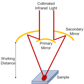
Reflection measurement is performed with a Cassegrain objective, which is different from a regular microscope objective. The Cassegrain objective (Figure 1) uses a primary and secondary mirror to send the IR beam onto the sample at 35o. IR reflective materials work best with this objective, while dark samples do not work as well.
Transmission Measurements of FTIR Microscopy
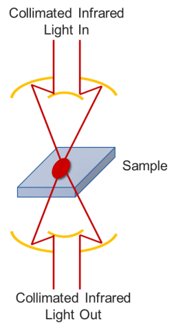
Transmission analysis of samples is probably the most common and most universal method of analyzing solids, liquids, and gases. Transmission measurements provide the highest sensitivity and best detection of all infrared sampling techniques. For transmission, two Cassegrain objectives are employed: focusing and condenser (Figure 2). The focusing works the same as the one for reflection. Light passes through the sample at the focal point and then hits the condenser which collimates the beam into the detector. Samples must be thin (less than 50 μm) and need to be in either a KBr pellet or diamond anvil cell. The focal planes of the Cassegrains are matched. Fibers, laminates, and thin films are often measured in transmittance mode.
ATR Measurements with FTIR Microscopy
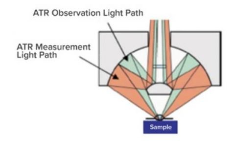
Attenuated total reflectance (ATR) uses special crystal materials in contact with a sample to get chemical information. The ATR (Figure 3) consists of focusing mirrors to hit the crystal at a 45o angle. The light then passes into the sample and reflected back into the spectrometer. To protect the objective, a pressure plate is required. Over pressure can damage some crystals, with the exception of diamond objectives. Diamond, ZnSe, and ZnS can be configured such that the sample can be seen when in contact with the sample.
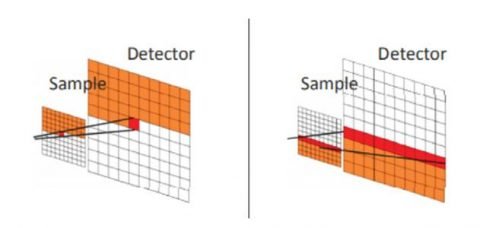
Grazing Angle
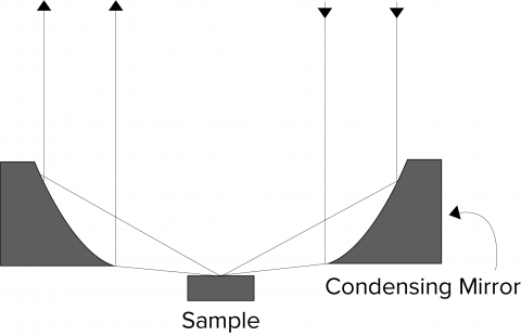
Coatings on ‘shiny’ substrates are excellent candidates for infrared reflection-absorption studies. As the coating gets thinner, incidence and collection angles can be varied from 45-75° until the ‘grazing’ angle is reached, generally considered to be 85° (Figure 4). The term ‘reflection absorption’ describes the progress of the incident beam as it passes through the coating, reflects from the substrate, and passes through the coating again before reaching the detector. As the incident and collection angles approach the grazing angle, the incident beam strikes the coating at shallower angles and the path length through the sample gets longer, enhancing the absorption intensity. Grazing angle reflection is used to examine the thinnest of surface coatings by ‘grazing’ the sample at a very shallow angle, the resulting longer sample path length providing greater sensitivity. Infrared reflection-absorption spectroscopy (IRRAS) is often used to study monolayer coatings on metals and other substrates. Limited quantitation can be made when evaluating the composition and thickness of the coatings.
Detectors
The many detectors that can be used in an FTIR microscope cover a wide wavelength range from the visible – (silicon photodiodes), NIR – (InSb or InGaAs), mid-IR – (TGS or MCT), far-IR – (Si bolometer). The IRT Series has a choice of standard detectors with the option of a second detector. The simplest detector, a Peltier cooled DLaTGS detector is used in the mid-IR region with good sensitivity, however, with much greater sensitivity an LN2 cooled mid-band MCT detector is better for measuring smaller microscopic areas. The optional second detector can be installed with a choice of either a fixed detector or a cassette system for interchangeable detectors, both can be selected from a wide range of options. To increase speed, especially for imaging or dynamic measurement a 16 element linear array detector (MCT or InSb) dramatically improves throughput (Figure 5).
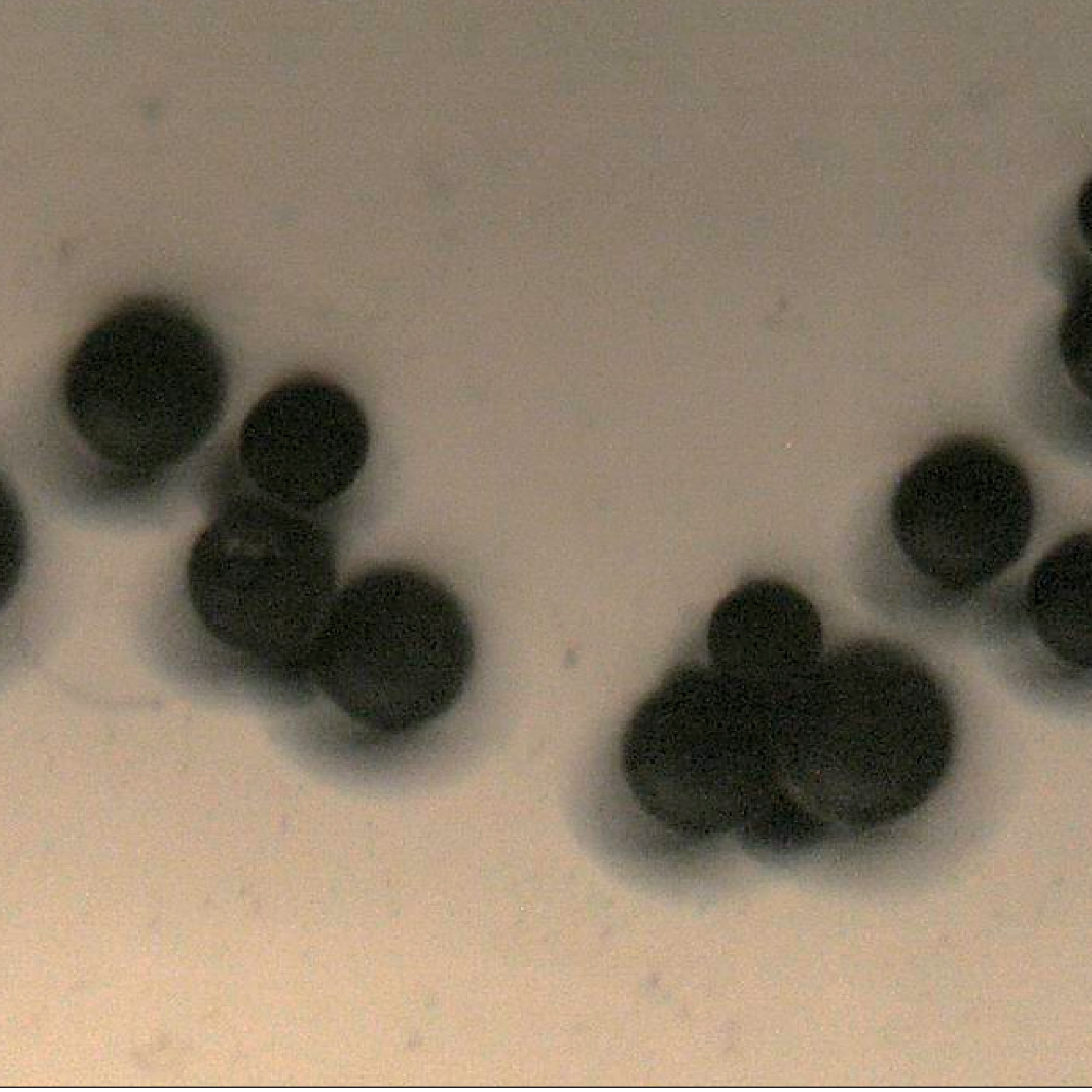
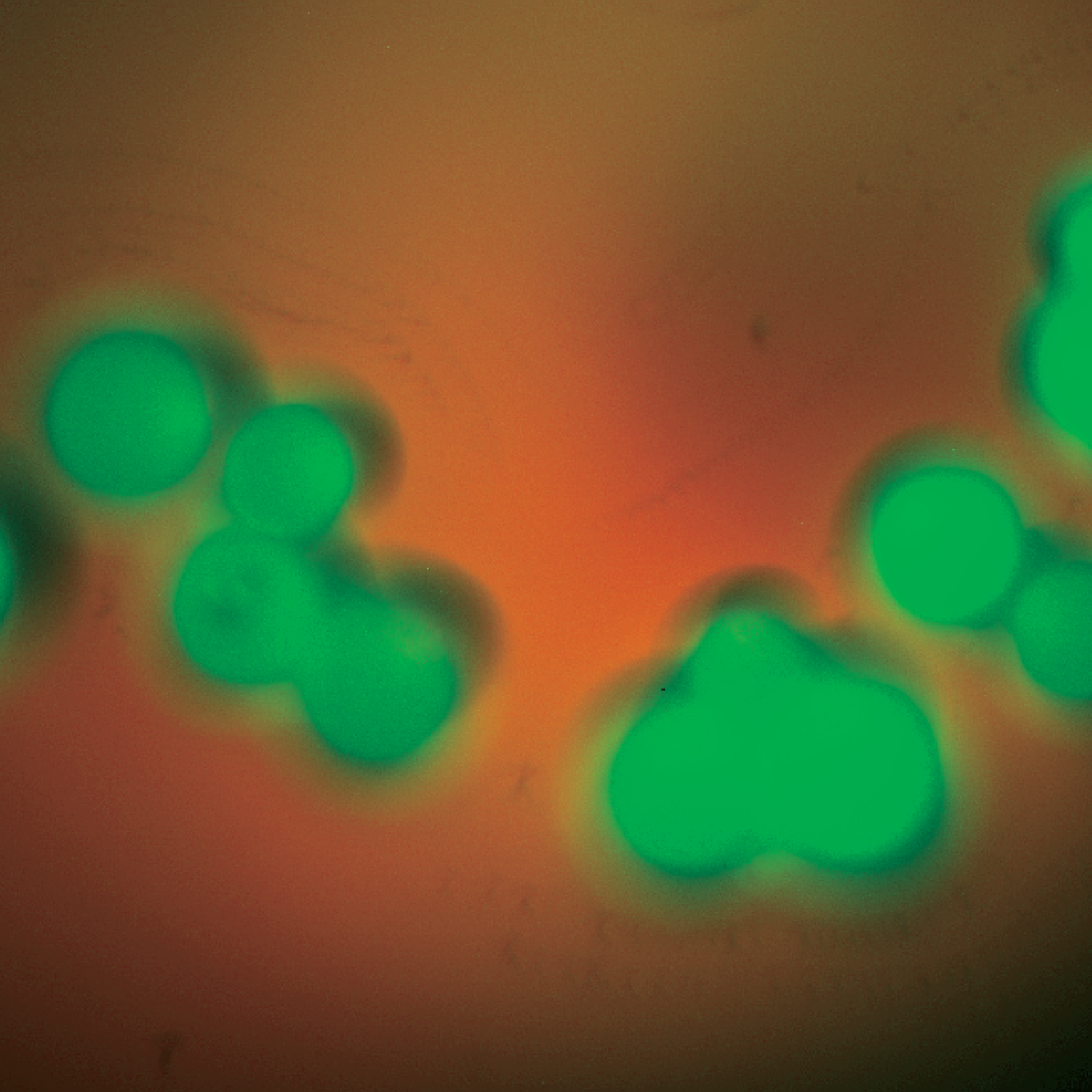
Optical Image
Fluorescence Image
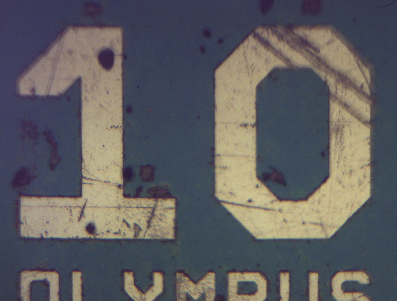
Optical Image
DIC Image
Optical Image
VPC Image
Complementary Techniques:
-
This technique can be used for chemical or molecular analysis encompassing depth profiling and mapping of samples with spatial resolution as little as 1 μm.
Confocal Raman Microscopy
-


FTIR spectroscopy is concerned with the vibration of molecules that contain a dipole moment.
FTIR Spectroscopy
-


An FTIR ATR method may be a suitable alternative and offers advantages such as minimal sample preparation, non-destructive measurement, and easy handling.
ATR FTIR