FTIR
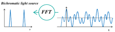
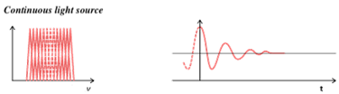
Frequency Spectrum Obtained from Interferogram
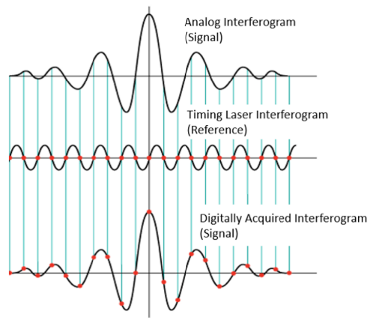
How is a digital interferogram acquired?
FTIR detectors observe interferograms as analog signals, but in order to perform a Fourier transform, the analog signals first need to be converted to digital signals. In a FTIR spectrometer, monochromatic light from a timing laser is used as an internal reference to track the position of the moving mirror using the precisely known wavelength of the laser. The intensity of the output interference signal is measured as a function of time. Each data point (or digital signal) in the infrared interferogram is taken when the timing laser interferogram has neither constructive nor destructive interference, allowing for an interferogram to be obtained at equal intervals (Figure 3). Helium-Neon (HeNe) lasers are the industry standard due to their excellent wavelength stability of 632.8 nm compared to solid-state or diode lasers. This laser stability allows for spectral additions, library searches, and other functions that require high wavenumber accuracy (Conne’s Advantage).
Instrumentation of a IR Spectrometer
A IR spectrometer consists of four major parts: a light source, an interferometer, a sample chamber, and a detector (Figure 4).
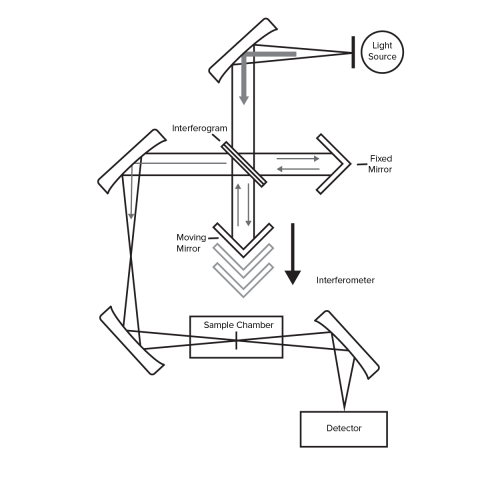
IR Spectrometer Michelson Interferometer
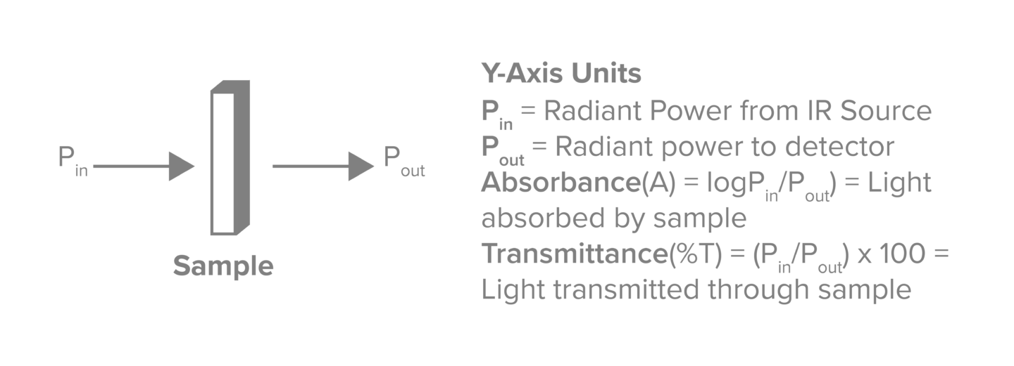
The interferometer is the heart of a IR spectrometer and consists of a beam splitter, a stationary mirror, and a moving mirror. The beam splitter is a semi-transparent mirror that splits a collimated beam of light into two different optical paths. Half of the light is transmitted to the moving mirror while the other half of the light is reflected to the stationary mirror. The two light beams are reflected from the moving and stationary mirror where they are recombined back at the beam splitter before passing through the sample chamber and onto the detector. The difference in the path of the mirrors causes constructive and destructive interference over the course of time it takes for the moving mirror to make a pass. The power of the beam (Pin) is attenuated by the sample due to absorbance by the sample (Pout), Figure 4. The relationship between power, transmittance, and absorbance can be seen in Figure 5.
IR Spectrometer Detectors
FTIR detectors are used to measure the transmitted or reflected light from a sample and convert it into an electrical signal. The type and material of the detector will determine the sensitivity and wavelength range of the data that can be acquired. Common FTIR spectrometer detectors include room temperature DLaTGS (220 – 15,000 cm-1) for routine analysis, liquid nitrogen cooled MCT (450 – 12,000 cm-1) for high sensitivity applications, silicon photodiodes (10,000 – 25,000 cm-1) for visible and near-IR measurements, and silicon bolometers (10 – 650 cm-1) for far-IR measurements. JASCO FTIR spectrometers come standard with a DLaTGS detector and have the option to install a second detector, such as a liquid nitrogen cooled MCT detector.
A DLaTGS (Deuterated L-Alanine doped Triglycine Sulphate) detector is a pyroelectric detector that generates an electrical signal based on temperature changes that are proportional to the intensity of IR radiation hitting the detector (Figure 6). DLaTGS detectors are standard for routine FTIR measurements since they have a linear response over a wide wavenumber range, are inexpensive, and can be used at ambient temperature.

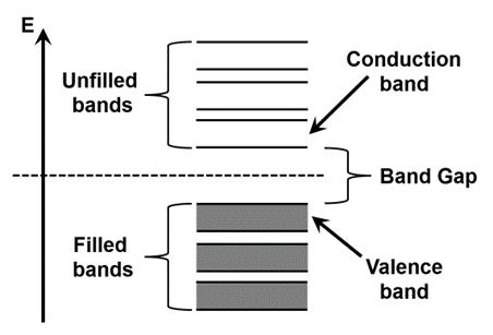
A MCT (Mercury Cadmium Telluride) detector is a semiconductor detector that generates an electrical signal based on the energy of excited electrons in the conduction band proportional to the intensity of IR radiation hitting the detector (Figure 7). MCT detectors are preferred over DLaTGS detectors for samples that require high sensitivity or speed since they produce a spectrum with a higher S/N ratio; however, MCT detectors have a nonlinear response over a reduced wavenumber range, can be easily saturated due to their sensitivity, are more expensive, and require liquid nitrogen cooling to reduce thermal noise.
Comparison of IR Spectrometer Optical Components
A list of light sources, beamsplitters, detectors, windows, and mirrors that are commonly used in FTIR spectrometers and their wavenumber ranges may be found in Table 1.